https://damow.net/building-a-thermal-camera/
Thermal cameras have always fascinated me. I think the
ability to view a part of the electromagnetic spectrum that is normally
hidden from us will always be a strange and exciting thing.
Unfortunately, they’re also quite expensive, especially if you’re buying one just for playing around with rather than using in some commercial capacity like thermal surveying or electronics testing.
I wanted to get started with thermography without a huge price tag, so I thought I’d go all in and build my own! Obviously, this was a hugely involved process so I’ll cover a bit of each aspect here. Feel free to ask questions down in the comments and I’ll do my best to answer!1
This is the business-end of a thermal camera. This is also the expensive, difficult-to-source bit. They are commercially available as components from electronics distributors such as Digi-Key, but I found that to be an expensive and difficult way to obtain them (the availability at the time I was trying to buy one was rather poor).
After watching a bunch of thermal camera-related Mike’s Electric Stuff videos on YouTube, I discovered that a good source of these might be the the small, smartphone-compatible thermal camera devices such as FLIR’s One and Seek Thermal’s Compact range.
A few clicks later and I found a broken FLIR One Gen. 2 on eBay for £75. The stated symptom was that it just didn’t power on at all, which I guessed might be down to a power/battery fault and hoped it wouldn’t affect the actual sensor module itself. These devices contain a FLIR Lepton 3 160x120 pixel microbolometer.
For £75, I think you’d be very hard-pressed to source an equivalent sensor - the Gen. 2 is now unavailable, but the current-gen FLIR One Pro with the same sensor resolution is £399.99.
As soon as the broken FLIR One arrived, I tore it down and retrieved the shining jewell that is the FLIR Lepton 3 sensor. I obtained a breakout board for the FLIR Lepton from Digi-Key for around £25 including shipping. The breakout board itself is a great little project by Pure Engineering. Once I had everything I needed, I hooked the whole thing up to a Raspberry Pi and used the Lepton 3 branch of the pylepton project on GitHub to verify that it was working. And it was! The gamble paid off - that could have been a wasted £75!
The display was quite easy to select. Chinese company ILI Technology produces a range of low-cost TFT display controllers. These seem very popular and well-supported in the hobbyist electronics market, so I picked a 2.8” TFT display based on the ILI9341 TFT LCD driver chip. In the hobbyist electronics market, these displays tend to come mounted on breakout PCBs with a number of other things added (resistive touch panel controller, SD card slot etc.). eBay is the best place to pick these up cheaply.
To drive the whole system, I ended up picking Espressif’s ESP32 platform. It has a fantastic ecosystem has integrated Wi-Fi and Bluetooth too. It also has two usable hardware SPI ports, which I required to drive both the display and the thermal camera module.
The particular development board I ended up choosing was a WEMOS LOLIN32 board. This one has a Lithium battery charging chip on-board and breaks out all the ESP32 pins that I required for the project.
I also wanted to be able to switch the whole device on and off with a power button/switch, while still being able to charge it via USB while off. I used a simple circuit with two PNP transistors to let the ESP32 control power to the thermal camera and display. I just built this circuit as small as I could on a scrap of veroboard for now.
I used FreeRTOS to structure the firmware into a task-oriented system in which one task reads data using the VoSPI (Video over SPI) interface from the thermal camera, while another task paints the current (valid) frame to the display via a second SPI port.
The current valid frame (
Each segment is presented to the
Unfortunately, this segment-based drawing process does make the GUI code a little more complex than one might expect as the drawing functions need to be aware of the segment that is currently being worked on. A rectangle, for instance may span several segments. This issue is holding up my implementation of text rendering a little, but I hope to have it working soon!
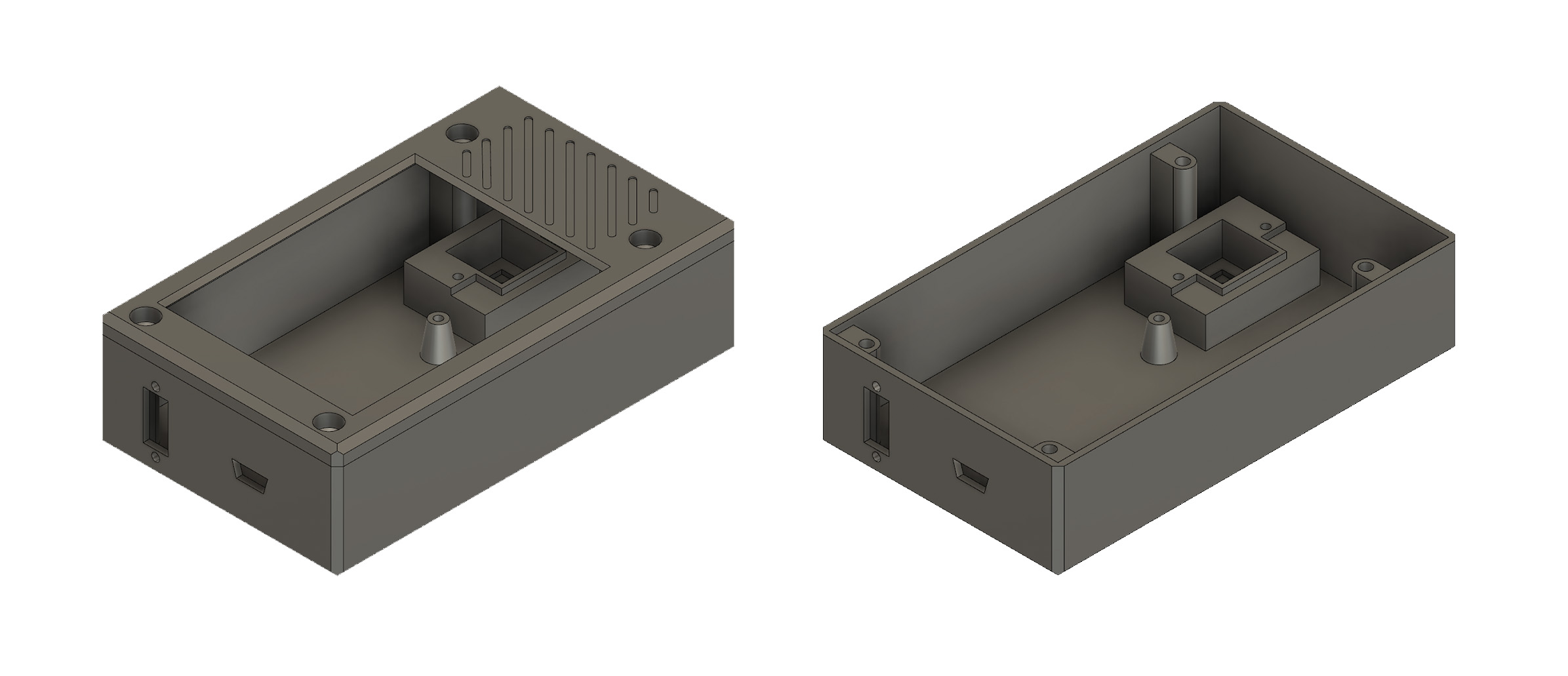
I wanted to produce a case that was small in size but would accommodate the display, battery and thermal camera module. I started by obtaining measurements for the parts I intended to use. Where these weren’t available (in the case of the LOLIN32 board) I took extensive measurements with Vernier callipers when producing my design.
I designed the case in Autodesk’s Fusion 360.
One of the challenges I ran into was how to shield the aperture in front of the thermal camera from dust and damage. Glass won’t cut it - it’s too opaque to the LWIR part of the electromagnetic spectrum we’re interested in for thermography. I found that two materials are typically used in these types of applications - Germanium and Zinc Selenide. I found a reasonably cheap source of Zinc Selenide optics and obtained a few samples but the results were unsatisfactory. Despite the AR coating on the windows, they seemed to reflect back a lot of the LWIR being radiated by the camera module itself.
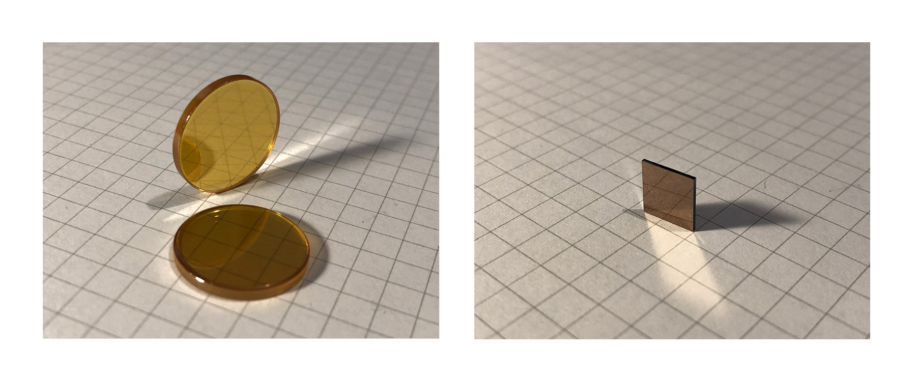
I settled on using the small piece of Germanium that protected the camera aperture in the original broken FLIR One camera I disassembled. It’s a little small (8mm x 8mm) but it definitely outperformed the ZnSE windows in terms of transmissivity and low-reflectivity.
The case design did take a few prototype runs to get right. 3 to be exact. Measurements and tolerances are hard to get right first time when 3D printing, so do keep that in mind for any kind of design work. After I produced a usable case, I mounted everything inside (which took some squeezing!). I think for V2 I’ll be giving myself a little more room inside the case. Even after using Fusion 360’s interference calculation features, I still appeared to have less space than I thought I would have.
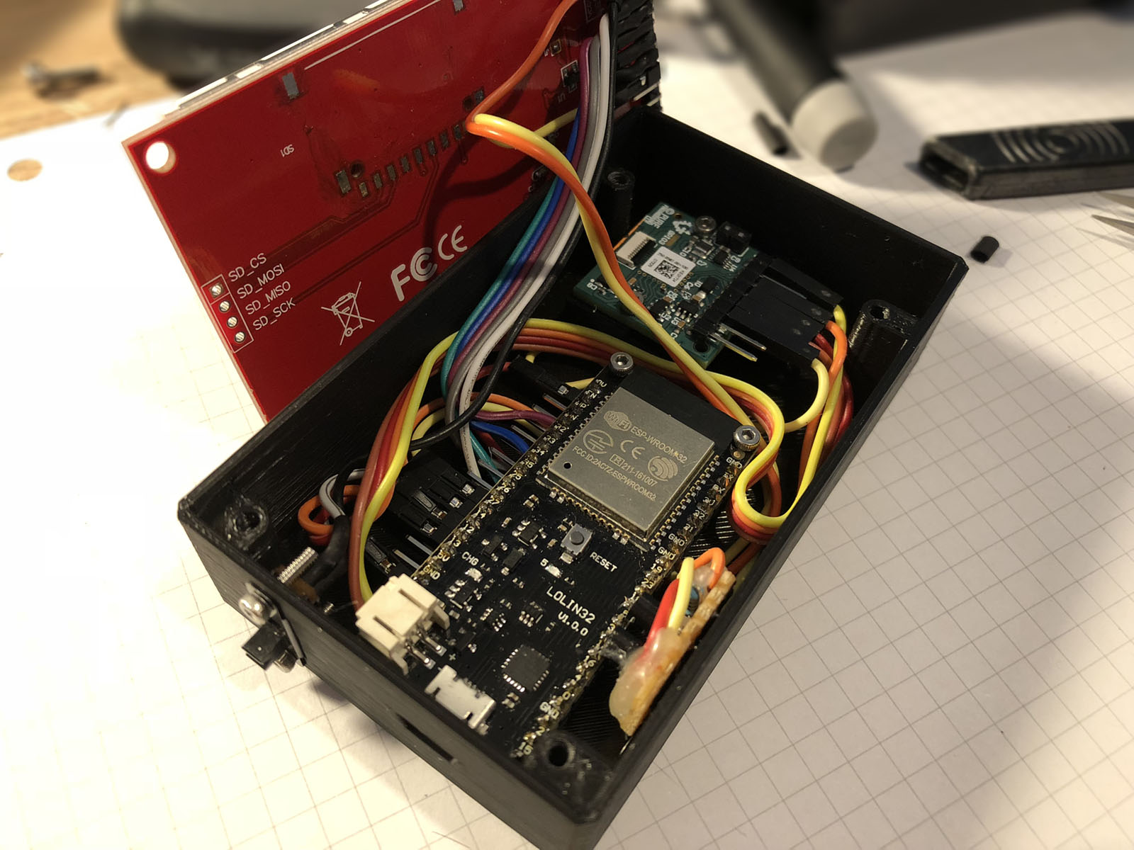
Inside, I used M2 machine screws to mount the ESP32 board and thermal camera breakout to the case. I didn’t want to damage the surface of the Germanium window with strong adhesives so I carefully cut 4 strips of Kapton tape to size and used those to secure the window in position.
Outside, I used M3 hex-drive machine screws to secure the case lid/display bezel down. One weakness was a lack of retaining clips meant that the bezel could bulge up slightly. My design allowed the screws to countersink in to the bezel so the result is really neat and tidy.
My design also allows access to the Micro-USB connector on the ESP32 development board, permitting charging and firmware flashing without disconnecting everything.
The next step is to hook up the thermal camera’s I2C interface too so that I can control the Flat Field Correction3 (FFC) functionality and display some telemetry data from the camera module itself (the temperature of the camera module, for example).
I still want to use the resistive touch panel on the display, but unfortunately it’s SPI too so it’ll need to share one of the ESP32’s SPI ports with either the display or the camera. I’ll have to assess which one of these will have the least impact on the performance of the video pipeline. I don’t want interaction with the touchscreen to visibly lag the video.
I think a further iteration of the case design is required too in order to resolve issues such as the lack of clips causing the front bezel to protrude in the middle. Additionally, the aperture for the thermal camera is a little small, or the thermal camera is too far from the aperture. When the case temperature is different to the scene temperature, one can see the edges of the aperture in the frame4.
Unfortunately, they’re also quite expensive, especially if you’re buying one just for playing around with rather than using in some commercial capacity like thermal surveying or electronics testing.
I wanted to get started with thermography without a huge price tag, so I thought I’d go all in and build my own! Obviously, this was a hugely involved process so I’ll cover a bit of each aspect here. Feel free to ask questions down in the comments and I’ll do my best to answer!1
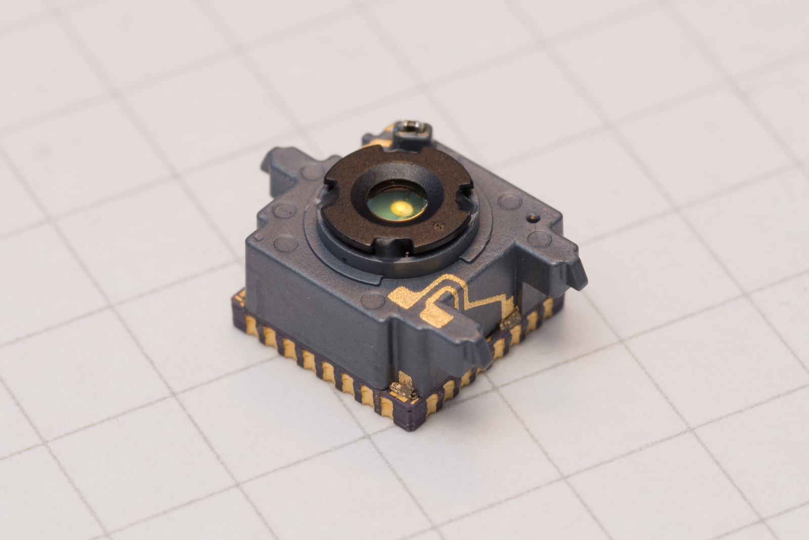
The Sensor
I started off trying to find a microbolometer.This is the business-end of a thermal camera. This is also the expensive, difficult-to-source bit. They are commercially available as components from electronics distributors such as Digi-Key, but I found that to be an expensive and difficult way to obtain them (the availability at the time I was trying to buy one was rather poor).
After watching a bunch of thermal camera-related Mike’s Electric Stuff videos on YouTube, I discovered that a good source of these might be the the small, smartphone-compatible thermal camera devices such as FLIR’s One and Seek Thermal’s Compact range.
A few clicks later and I found a broken FLIR One Gen. 2 on eBay for £75. The stated symptom was that it just didn’t power on at all, which I guessed might be down to a power/battery fault and hoped it wouldn’t affect the actual sensor module itself. These devices contain a FLIR Lepton 3 160x120 pixel microbolometer.
For £75, I think you’d be very hard-pressed to source an equivalent sensor - the Gen. 2 is now unavailable, but the current-gen FLIR One Pro with the same sensor resolution is £399.99.
As soon as the broken FLIR One arrived, I tore it down and retrieved the shining jewell that is the FLIR Lepton 3 sensor. I obtained a breakout board for the FLIR Lepton from Digi-Key for around £25 including shipping. The breakout board itself is a great little project by Pure Engineering. Once I had everything I needed, I hooked the whole thing up to a Raspberry Pi and used the Lepton 3 branch of the pylepton project on GitHub to verify that it was working. And it was! The gamble paid off - that could have been a wasted £75!
Hardware
I wanted to build a self-contained & portable thermal camera device with an integral display and processor, all powered by a battery. While I had written a working driver for the camera in C for Linux just usingspidev (which even supports streaming the live video to a JavaScript-based web client via ØMQ), that wouldn’t suit a battery-powered setup.The display was quite easy to select. Chinese company ILI Technology produces a range of low-cost TFT display controllers. These seem very popular and well-supported in the hobbyist electronics market, so I picked a 2.8” TFT display based on the ILI9341 TFT LCD driver chip. In the hobbyist electronics market, these displays tend to come mounted on breakout PCBs with a number of other things added (resistive touch panel controller, SD card slot etc.). eBay is the best place to pick these up cheaply.
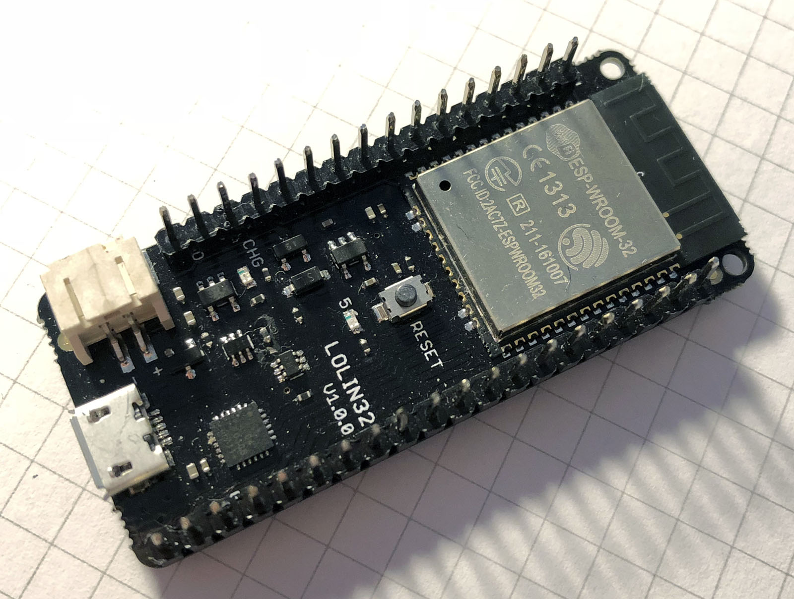
To drive the whole system, I ended up picking Espressif’s ESP32 platform. It has a fantastic ecosystem has integrated Wi-Fi and Bluetooth too. It also has two usable hardware SPI ports, which I required to drive both the display and the thermal camera module.
The particular development board I ended up choosing was a WEMOS LOLIN32 board. This one has a Lithium battery charging chip on-board and breaks out all the ESP32 pins that I required for the project.
I also wanted to be able to switch the whole device on and off with a power button/switch, while still being able to charge it via USB while off. I used a simple circuit with two PNP transistors to let the ESP32 control power to the thermal camera and display. I just built this circuit as small as I could on a scrap of veroboard for now.
Firmware
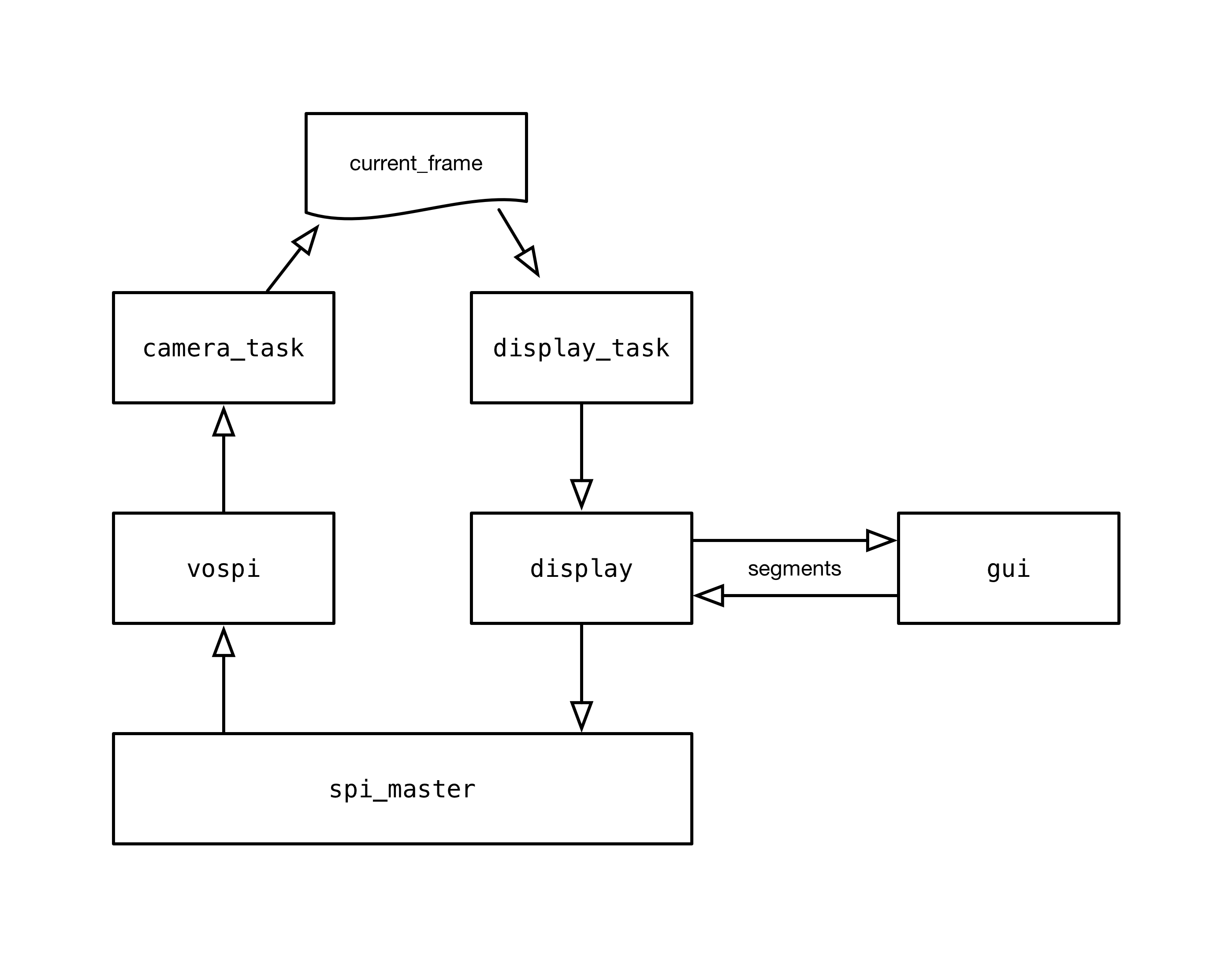
I based the firmware2 around my existing Linux driver for the FLIR Lepton 3. The code was relatively easy to port to ESP32 - at a high level it just involved swapping out thespidev API for the ESP32’s SPI Master API.I used FreeRTOS to structure the firmware into a task-oriented system in which one task reads data using the VoSPI (Video over SPI) interface from the thermal camera, while another task paints the current (valid) frame to the display via a second SPI port.
The current valid frame (
current_frame)
is held in a structure shared between the two tasks and protected by a
semaphore. The display is exactly double the resolution of the thermal
camera in both dimensions, so that made things work out quite nicely in
terms of scaling the thermal camera frame to the display.camera_task captures frames
from the thermal camera using FLIR’s VoSPI protocol. This task handles
any (re)synchronisation that needs to take place with the video stream
and only updates current_frame when a new valid frame is captured.display_task renders current_frame
to the display as four segments (they are presented this way by the
camera’s VoSPI interface and it suited me to keep this arrangement
rather than having another full display frame buffer tying up memory).Each segment is presented to the
gui subsystem before being painted to the display. The gui
subsystem can draw basic shapes and annotations on top of the image
before it is shown. These annotations are stored in a linked list and
the API of the gui subsystem provides operations to add, remove and modify entries. For instance, as a demo, I’ve added another task - user_task
- to handle UI. It currently just renders a single green square in the
top-left corner and toggles its visibility once per second.Unfortunately, this segment-based drawing process does make the GUI code a little more complex than one might expect as the drawing functions need to be aware of the segment that is currently being worked on. A rectangle, for instance may span several segments. This issue is holding up my implementation of text rendering a little, but I hope to have it working soon!
Case Design
Lately I’ve been getting into the more tangible side of creating. A few months ago, I finally boarded the 3D printing bandwagon with the purchase of my Original Prusa i3 MK2S, and I’ve been having a ton of fun with it since!I wanted to produce a case that was small in size but would accommodate the display, battery and thermal camera module. I started by obtaining measurements for the parts I intended to use. Where these weren’t available (in the case of the LOLIN32 board) I took extensive measurements with Vernier callipers when producing my design.
I designed the case in Autodesk’s Fusion 360.
One of the challenges I ran into was how to shield the aperture in front of the thermal camera from dust and damage. Glass won’t cut it - it’s too opaque to the LWIR part of the electromagnetic spectrum we’re interested in for thermography. I found that two materials are typically used in these types of applications - Germanium and Zinc Selenide. I found a reasonably cheap source of Zinc Selenide optics and obtained a few samples but the results were unsatisfactory. Despite the AR coating on the windows, they seemed to reflect back a lot of the LWIR being radiated by the camera module itself.
I settled on using the small piece of Germanium that protected the camera aperture in the original broken FLIR One camera I disassembled. It’s a little small (8mm x 8mm) but it definitely outperformed the ZnSE windows in terms of transmissivity and low-reflectivity.
The case design did take a few prototype runs to get right. 3 to be exact. Measurements and tolerances are hard to get right first time when 3D printing, so do keep that in mind for any kind of design work. After I produced a usable case, I mounted everything inside (which took some squeezing!). I think for V2 I’ll be giving myself a little more room inside the case. Even after using Fusion 360’s interference calculation features, I still appeared to have less space than I thought I would have.
Inside, I used M2 machine screws to mount the ESP32 board and thermal camera breakout to the case. I didn’t want to damage the surface of the Germanium window with strong adhesives so I carefully cut 4 strips of Kapton tape to size and used those to secure the window in position.
Outside, I used M3 hex-drive machine screws to secure the case lid/display bezel down. One weakness was a lack of retaining clips meant that the bezel could bulge up slightly. My design allowed the screws to countersink in to the bezel so the result is really neat and tidy.
My design also allows access to the Micro-USB connector on the ESP32 development board, permitting charging and firmware flashing without disconnecting everything.
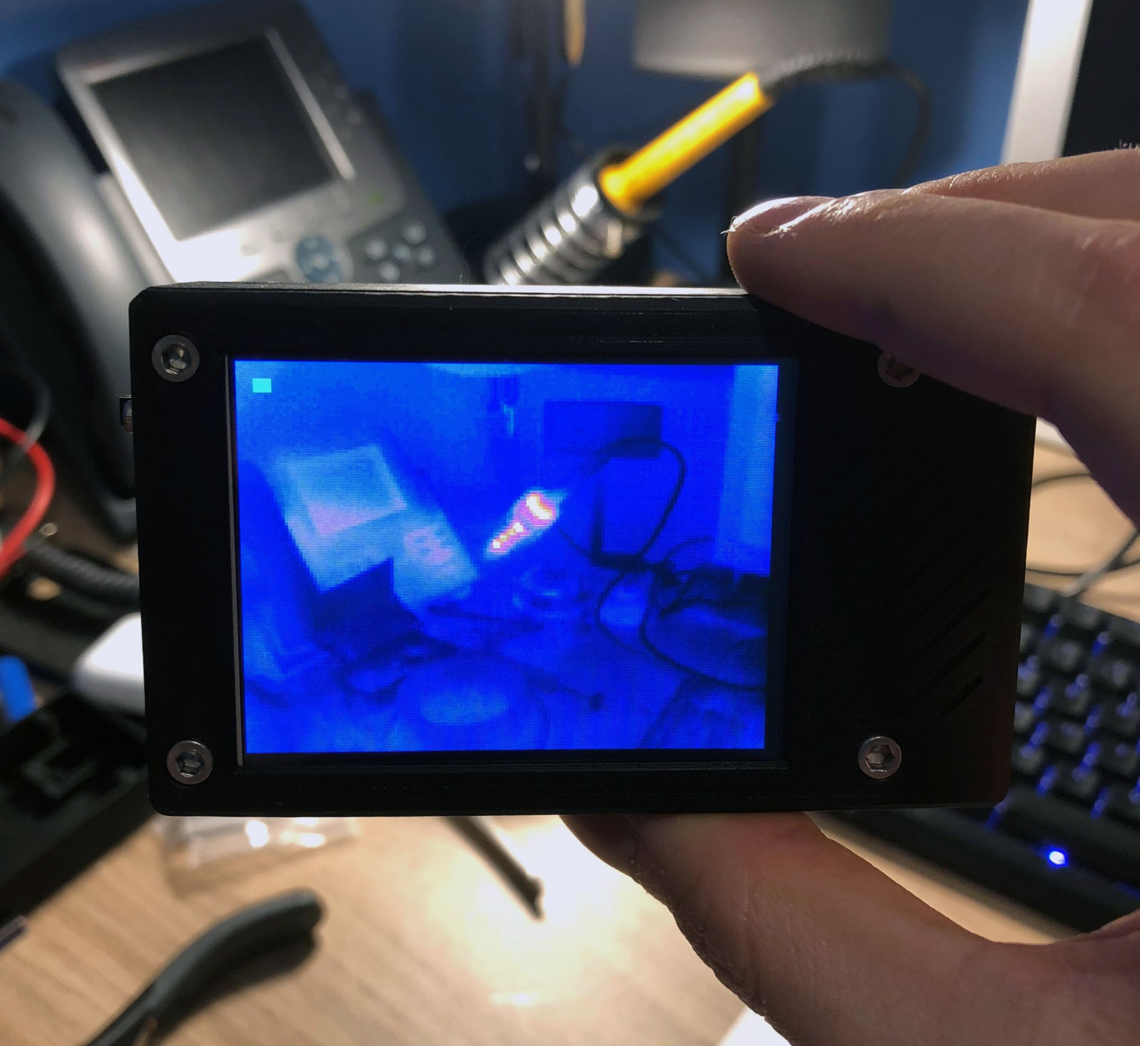
The Finished Product
The finished product works really well. I’m still adding to the firmware so it’s still slowly improving too. With a 1300mAh Li-Po cell fitted, it has great battery life. Powered off, the system has a ~250µA quiescent current draw (with the ESP32 in the deep sleep state) from the Li-Po cell. With the display and camera on and the video pipeline running, the whole system has a ~230mA current draw from the Li-Po cell.The next step is to hook up the thermal camera’s I2C interface too so that I can control the Flat Field Correction3 (FFC) functionality and display some telemetry data from the camera module itself (the temperature of the camera module, for example).
I still want to use the resistive touch panel on the display, but unfortunately it’s SPI too so it’ll need to share one of the ESP32’s SPI ports with either the display or the camera. I’ll have to assess which one of these will have the least impact on the performance of the video pipeline. I don’t want interaction with the touchscreen to visibly lag the video.
I think a further iteration of the case design is required too in order to resolve issues such as the lack of clips causing the front bezel to protrude in the middle. Additionally, the aperture for the thermal camera is a little small, or the thermal camera is too far from the aperture. When the case temperature is different to the scene temperature, one can see the edges of the aperture in the frame4.
-
The paper used in the background of the macro images in this post is 5mm square-ruled. ↩
-
My firmware is available on GitHub. Feel free to have a hack! ↩
-
When the camera initially starts up (and at a number of other
times too), it performs a correction to improve the uniformity of the
image. This involves closing the shutter to obtain a “flat field” and
taking a sample. This helps to correct for any thermal gradient present
on the FPA (Focal Plane Array) itself. ↩
-
The thermal camera has quite a wide FoV - nominally 56º. See p. 48 of http://www.flir.com/uploadedFiles/OEM/Products/LWIR-Cameras/Lepton/Lepton-3-Engineering-Datasheet.pdf ↩
Comments
Post a Comment