http://maxembedded.com/2013/08/04/how-to-build-an-ir-sensor/


So this was it for this post.
Don’t forget to share your views, responses and queries in the comment
box below. You can subscribe via email to stay updated and get feeds
right into your inbox as well!
What is an IR sensor?
An IR sensor is a device which detects IR
radiation falling on it. There are numerous types of IR sensors that
are built and can be built depending on the application. Proximity
sensors (Used in Touch Screen phones and Edge Avoiding Robots), contrast
sensors (Used in Line Following Robots) and obstruction
counters/sensors (Used for counting goods and in Burglar Alarms) are
some examples, which use IR sensors.
Before reading ahead, I would suggest you to go through this small post by Mayank on sensor fundamentals. It would help you in understanding the concepts discussed in this post.
Working Mechanism
An IR sensor is basically a device which
consists of a pair of an IR LED and a photodiode which are collectively
called a photo-coupler or an opto-coupler. The IR LED emits IR
radiation, reception and/or intensity of reception of which by the
photodiode dictates the output of the sensor. Now, there are so many
ways by which the radiation may or may not be able to reach the
photodiode. Let’s discuss a few.
Direct incidence
We may hold the IR LED directly in front
of the photodiode, such that almost all the radiation emitted, reaches
the photodiode. This creates an invisible line of IR radiation between
the IR LED and the photodiode. Now, if an opaque object is placed
obstructing this line, the radiation will not reach the photodiode and
will get either reflected or absorbed by the obstructing object. This
mechanism is used in object counters and burglar alarms.
Indirect Incidence
High school physics taught us that black
color absorbs all radiation, and the color white reflects all radiation.
We use this very knowledge to build our IR sensor. If we place the IR
LED and the photodiode side by side, close together, the radiation from
the IR LED will get emitted straight in the direction to which the IR
LED is pointing towards, and so is the photodiode, and hence there will
be no incidence of the radiation on the photodiode. Please refer to the
right part of the illustration given below for better understanding.
But, if we place an opaque object in front the two, two cases occur:
Reflective Surface
If the object is reflective, (White or
some other light color), then most of the radiation will get reflected
by it, and will get incident on the photodiode. For further
understanding, please refer to the left part of the illustration below.
Non-reflective Surface
If the object is non-reflective, (Black
or some other dark color), then most of the radiation will get absorbed
by it, and will not become incident on the photodiode. It is similar to
there being no surface (object) at all, for the sensor, as in both the
cases, it does not receive any radiation.

Illustration Indirect Incidence of IR radiation
Where do we use them?
Proximity Sensors
We use reflective indirect incidence
for making proximity sensors. The radiation emitted by the IR LED is
reflected back on the photodiode by an object. Closer the object, higher
will be the intensity of the incident radiation on the photodiode.
This intensity is made analogous to a voltage by a circuit, which is
then used to determine the distance.
Proximity sensors find use in Touch
Screen phones, apart from many other devices. In a Touch Screen Phone,
the touch screen needs to disabled when it is held near the ear, while
in use, so that even if the cheek makes contact with the tough screen,
there is no effect.
Line Follower Robots
IR sensors are the main triggers of the
whole line following robot’s action mechanism. IR sensors are the ones
which detect the color of the surface underneath it and send a signal to
the microcontroller or the main circuit which then takes decisions
according to the algorithm set by the creator of the bot. The sensors
used in them are based on reflective/non-reflective indirect incidence.
The IR LED emits IR radiation, which in normal state gets reflected
back to the module from the white surface around the black line, which
gets incident on the photodiode. But, as soon as the IR radiation falls
on the black line, the IR radiation gets absorbed completely by the
black color, and hence there is no reflection of the IR radiation going
back to the sensor module.
Item Counter
This is based on direct incidence
of radiation on the photodiode. Whenever an item obstructs the
invisible line of IR radiation, we make an increment in the value of a
stored variable in a computer/microcontroller which may be indicated by
LEDs, Seven Segment Displays, LCDs etc.
These counters are often used in
monitoring systems of large factories, where products on conveyor belts,
that are loaded/unloaded are counted.
Burglar Alarm
This is also based on direct incidence of
radiation on the photodiode. Here, the IR LED is fitted on one side of
the door frame, and the photodiode on the other, such that in normal
condition, the IR radiation emitted by the IR LED falls on the
photodiode directly. As soon as a person obstructs the IR path, the
alarm goes off. This alarm can be switched on at night, and switched off
in the day, during normal use of the door.
This mechanism is used extensively in
security systems and is replicated on a smaller scale for smaller
objects, such as exhibits in an exhibition, etc.
Analog vs Digital sensor
Now that you know all about IR sensors,
their working mechanism and applications, it’s a good time to talk about
analog and digital sensors. But first let’s talk about what analog and
digital are.
Analog data
Analog data is basically a continuous
stream of data, without discrete levels. It can be used to express
anything, voltage, temperature, pressure etc. provided it is not in
steps of discrete levels. What we see around us, or hear, or anything
that is sensed by our sense organs is a continuous stream of input, and
hence is analog. For example, let’s a consider a stationery car. We are
the driver of the car, and we want to attain a speed of 60 Km/hr.
Obviously, we can’t attain this speed instantly, we will have to move up
from 0 to 60 Km/hr gradually, no matter how fast we accelerate. So, all
the different values of speeds that we attain in this process are all
analog data as they can be anything, and are not discrete. Music too, is
analog, since each note that we hear is a sine wave, which we all know
is continuous.

Analog sensor
If we make an analog IR sensor, then we
will get an analog output in terms of voltage which can hold any value
between 0 volts and the voltage that we have provided as Vcc. Higher the
intensity of the radiation falling on the photodiode, higher will be
the output voltage. One such sensor is the one in the photograph above.
It is a sensor I found in a very expensive Robotics Kit. It also has an
LDR (Light Dependent Resistor) on board with a transistor amplifier to
amplify the output of the LDR which is used to detect ambient light.
We can use analog sensors to estimate the
distance of an object from the sensor, where distance will be inversely
proportional to the output voltage. We can do so by interfacing our
sensor with a microcontroller which is capable of receiving analog data
and program it to calculate the distance. Analog sensors are used, and
can be used in many other applications.
Making an Analog IR sensor is relatively
easier than making a digital one. All we need is an IR LED and a
photodiode, both with series resistors with them. To make one, just
remove everything on the right (starting from the IC) of the
circuit diagram given below in the “How Does It Work” section. That
means you will only need 4 components, namely, the 150 and 10K
resistors, and the IR LED and the Photodiode. The output of this sensor
will have to be taken from the junction of the photodiode and the 10K
resistor, which in the circuit diagram given below, is connected to the
3rd pin of the IC.
Digital Data
Digital Data is expressed in terms of two
discrete values, 0 and 1. The smallest unit of digital data is called a
‘bit’. One bit of digital data can only be one of two values, 0 and 1,
unlike analog data, where one unit of analog data can hold any value
possible. For example, there is a toy car designed such that the remote
control has only 2 buttons. Both of them will make the car move forward,
one with a speed of 30 Km/hr and the other with 60Km/hr. We see here
that we don’t have an option to move the car at any other speed other
than the ones defined above, there are only two discrete levels of
speed. This is how digital data is in nature.
Analog data can be converted into digital
data using Analog to Digital Converters (ADC). Our Music CD players at
home are nothing but highly sophisticated Analog to Digital Converters,
since they convert Analog data (Music) on a CD to digital data, process
the data, amplify it, reconvert the processed data to analog data and
output the music via speakers. In hardware, digital information can be
expressed as voltages, i.e, 0 Volts and 5 Volts. They are also known as
digital logic high (represented by ’1′) for 5 V and digital logic low
(represented by ’0′) for 0 Volts.
If we want to make a digital sensor, we
will have to use a device which creates discrete levels and only gives
out 0 and 5 volts as output. This device in the design that we are using
is the LM358M, which a Dual Op-Amp. Any General Purpose Op-amp with
similar gain and operating voltages can be used, like the LM324M. This
digital output of the sensor, can be fed into the GPIO (General Purpose
Input/Output) pins of any microcontroller. To learn how to use AVR
microcontollers to convert and process analog data, please refer to this
post on the ADC of the AVR.
In this post, we are primarily making a digital IR sensor.
What do we need?
- IR LED
- Photodiode
- LM-358M (Op-Amp)
- 2 x 150 Ω Resistance
- 1 x 10 kΩ Resistance
- 1 x 10 kΩ Variable Resistance (Potentiometer/Preset)
- 5 Volt power source
- Wires
- General purpose PCB or bread board (Picture Below)

PCB
Some things you need to know
IR LED

IR LED
An IR LED is a type of LED which emits
light in the frequency range of Infra-Red, hence the name ‘IR’ LED.
Please note that Infra-Red radiation is invisible to the human eye, and
hence we cannot see an IR LED emit it when it actually is. But there is a
way to see IR radiations, if you want to. If you look at IR radiation
through the lens of a camera, you will be able to see it. Apart from
this, in every other sense an IR LED works exactly like an ordinary LED
(Look at the picture above), consumes a current of about 20mA and
operates on around 3V DC. please refer to the diagram given below for
details on connections of the IR LED, as well as the ordinary LED, if
you choose to use one.

Detailed Diagram of an LED
Photodiode
A photodiode is a type of diode which
detects light. We can think of it as having a very high resistance when
no light is falling on it. As we increase the intensity of light
incident on it, the current through it gradually increases too. So, by
increasing the incident light on a photodiode, we convert it into a
normal low value resistor, which conducts current. We should note here
that a photodiode looks exactly like an LED, sometimes, with a dark blue
or black film on the outer casing (Please look at the picture below),
but we make use of it in reverse bias, that means opposite in
configuration as in the case of an LED. You can refer to the diagram
above for the connections of the photodiode, but remember to connect it
in reverse bias as shown in the circuit diagram given in the “How does
it work?” section below.

Photodiode
IC Op-Amp LM358M (as a voltage comparator)
LM358M is a general purpose Dual
Operational Amplifier (Op-Amp). Knowing the working of an Op-amp here is
really of no use to us, as we are not using it as an amplifier as such,
so we will only be talking about how we use it here in the IR sensor
circuit, what it does, but not much about how it does it. So basically,
we use it to compare two voltages, one is fixed and the other varies
with an environmental parameter. If the parameter controlled voltage is
higher than the fixed the voltage, then the IC should give one output,
and if it is lower than the fixed voltage, then it should give another
output. So, we see that the IC gives only two types of outputs, which we
design to be 5 Volts and 0 Volts. This makes our sensor digital.
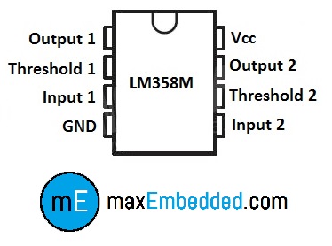
Pin Configuration for LM358M
Now, we know how to use our Op-Amp, so
let’s talk about how to connect components to it. This IC is an 8 pin
IC. Check the illustration above for the pin layout. Output (pin 1) is
where we get the 5/0 Volts, Threshold (pin 2) is the fixed voltage,
Input (pin 3) is where we supply our environment controlled voltage, and
pin 4 & 8 are used to power up the IC. The best part about this IC
is that it is a Dual Op-Amp, so you can make two
completely separate IR sensors using the same IC! All you need to do is
mirror all the connections on the lower three terminals of the other
half of the IC (Refer to the pin diagram of the IC).
NOTE: The way we are using this IC
here and the pin configuration I have shown here is not how an Op-Amp
is used traditionally, we are actually manipulating the IC to work as a
voltage comparator. Please do not use the above explanation as your
guide to studying Operational amplifiers.

LM358M
Variable Resistor
A variable resistor is a 3 pin device
which is used to vary resistance. In this circuit, we use it to
calibrate the IR sensor according to the environment. We give Vcc and
GND to the terminals which are close together and connect the center
terminal to the threshold of the IC (Assuming you are using the small
triangular PCB mountable package like the one shown below).

Variable Resistor
How does it work?
If the IR LED emissions become incident
on the photodiode, the photodiode’s resistance comes down to a finite
value. The drop across the 10K series resistor is what we use as the
input, which is compared with the threshold. The point to be noted here
is that more the incident radiation on the photodiode, less will be the
drop across it, and hence more will be the drop across the series
resistor. If the voltage developed across the resistor is greater than
the threshold set by us, the output of the IC will be high, else it will
be low. Hence, if our reflected radiation is never strong enough to be
greater than the threshold and we have a constant low as output, we can
reduce the threshold voltage by turning the “minus shaped” slit in the
variable resistance towards its terminal where we connected Gnd. In case
our threshold is very low and the output is always high in spite of no
radiation or if it is just too sensitive, then you can increase the
threshold by turning the slit the other way. When the emissions are
absorbed by a black surface, the resistance of the photodiode becomes
very high due to no incidence of IR emissions on it, and the output
remains low. I like to use an LED to indicate the output, even if I have
the output going to the main circuit, but it is totally up to you when
you make it.
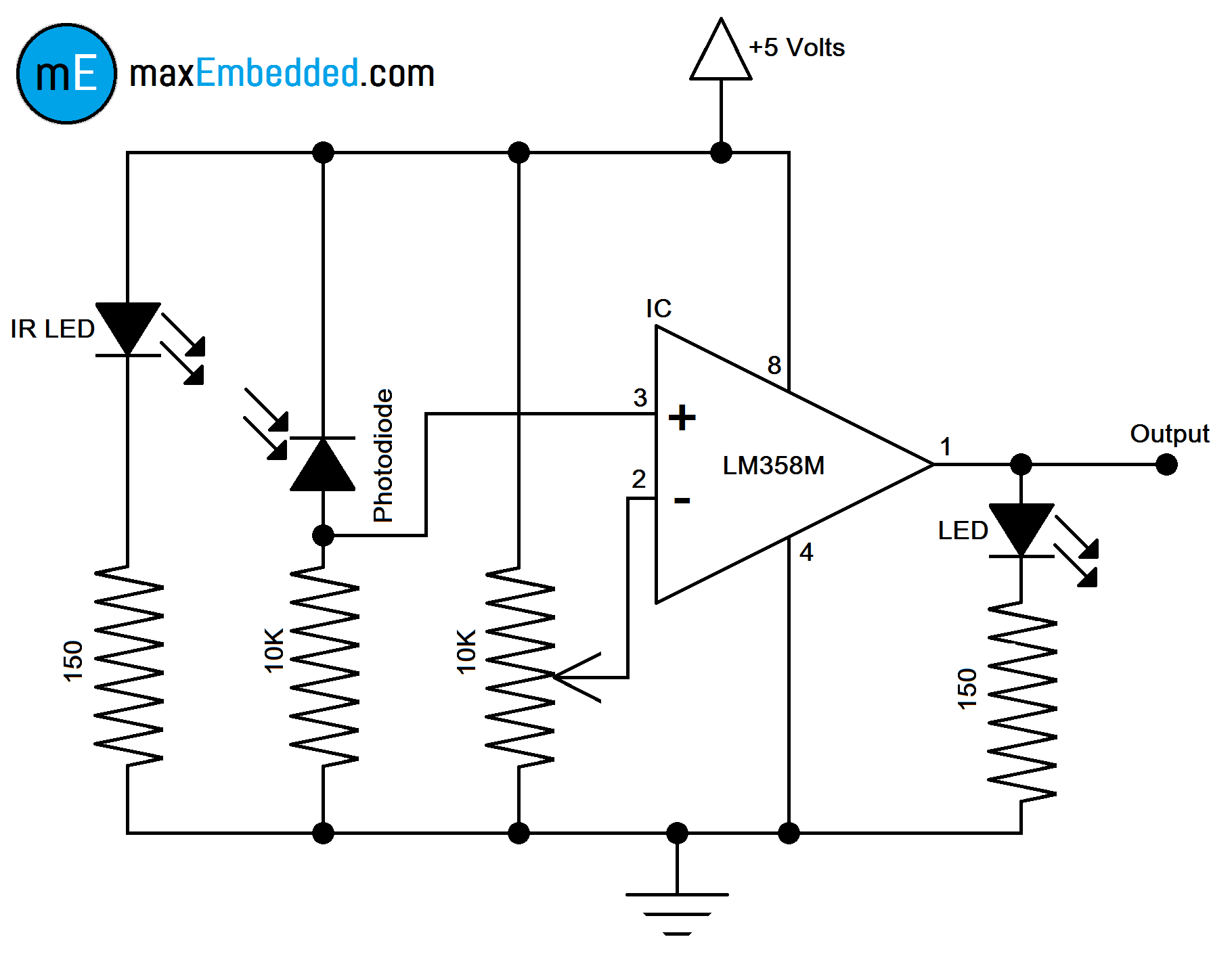
Circuit Diagram

Circuit Discription
Completed IR Sensor
The sensor board that you see in the
pictures is the one I made. It’s pretty small, not as small as the ones
available in the market which are pre-made on fabricated PCBs, but very
close. I have designed it in such a way that I will need to supply it 5
Volts DC via the two male header pins in the bottom of the board. The
output will have to be taken from the male header pin on the right side
of the board and routed to the main circuit using a connecting cable.
The LED above this output male header is the one that indicates a
reflective surface in front of the board by glowing, I chose the color
of the LED to be red. You may choose to make a breakout board (like I
did), that can be used in any IR sensing application, or you may want to
make one on the same PCB as your main circuit. You may want to add
multiple sensors to the same board by just repeating the circuit over
and over again, as many times as you want. (Remember, with one LM358M,
you can make two independent IR Sensors).

Final Board
Sample Video
This is a sample video of me testing the
IR sensor that i made. I test it by differentiating the colors black and
white. I count the number of black lines, and if the count value is a
prime number, i make an LED glow. The code for the same is given below.
It is for the AVR Atmega16 Microcontroller in Embedded C/C++.
Sample Code
This is a sample code written by me for
the AVR Atmega16 Microcontroller. I first check if the sensor has
detected a non-reflective surface/obstacle. Then I increment the value
of a variable at every detection. If the number of times the sensor has
detected something is prime, then an LED glows, and if it is composite,
the LED turns off. The code was written in and compiled using Atmel Studio 6. The code is pretty simple and straightforward if you are familiar with the AVR I/O operations.
1
2
3
4
5
6
7
8
9
10
11
12
13
14
15
16
17
18
19
20
21
22
23
24
25
26
27
28
29
30
31
32
33
34
35
36
37
38
39
40
| #define F_CPU 1000000UL#include <avr/io.h>int ch_prime(int); //Prototyping the function for testing a number to be prime or notint main(void){ uint8_t num=0, res; //Creating variables 'num' & 'res' for storing the number of detections & result of the function respectively DDRA &= ~(1<<0); //Setting 0th pin of Port A as input DDRD |= (1<<0); //Setting 0th pin of Port D as output while(1) { if (bit_is_set(PINA, 0)) //Checking if the sensor has detected something in front of it { while (bit_is_set(PINA, 0)); // We use the 'While' function to make sure that one detection increments the value of num by only one value res = ch_prime(++num); //Incrementing the value of num and sending it to the function which tests it for being a prime number if (res==1) PORTD |= (1<<PIND0); //If returned value is 1, indicate prime number by pulling the 0th pin on Port D High else PORTD &= ~(1<<PIND0); //If returned value is 0, indicate composite number by pulling the 0th pin on Port D Low } else continue; //If sensor has nothing in front of it, continue detecting }}int ch_prime(int num){ int i; //Declaring variable 'i' to use in the for loop for (i=2;i<num;i++) //Run the loop for the value of i from '2' to 'num-1' { if (num%i==0) //Check and compare to 0 the remainder when dividing num by i, if 0, then composite number return(0); //If Number is composite, return 0 } if (i==num) //Compare the value of i to num, if same, then prime number return(1); //If number is prime, return 1} |
Comments
Post a Comment