https://engineering.fb.com/2021/08/11/open-source/time-appliance/
Open-sourcing a more precise time appliance

- Facebook engineers have built and open-sourced an Open Compute Time Appliance, an important component of the modern timing infrastructure.
- To make this possible, we came up with the Time Card — a PCI Express (PCIe) card that can turn almost any commodity server into a time appliance.
- With the help of the OCP community, we established the Open Compute Time Appliance Project and open-sourced every aspect of the Open Time Server.
In March 2020, we announced that we were in the process of switching over the servers in our data centers (together with our consumer products) to a new timekeeping service based on the Network Time Protocol (NTP). The new service, built in-house and later open-sourced, was more scalable and improved the accuracy of timekeeping in the Facebook infrastructure from 10 milliseconds to 100 microseconds. More accurate time keeping enables more advanced infrastructure management across our data centers, as well as faster performance of distributed databases.
The new NTP-based time architecture uses a Stratum 1 — an important component that is directly linked to an authoritative source of time, such as a global navigation satellite system (GNSS) or a cesium clock.
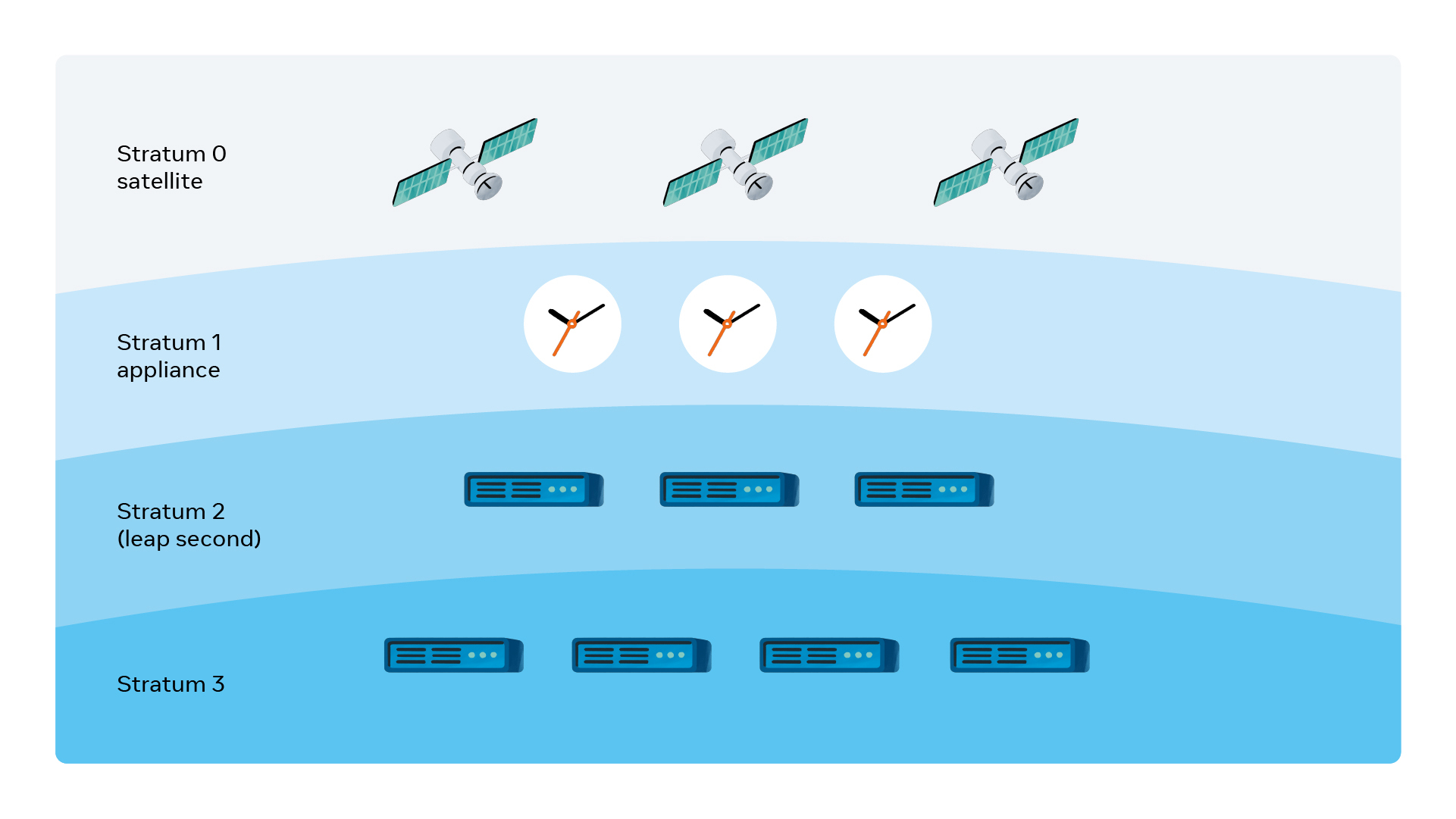
Many companies rely on public NTP pools such as time.facebook.com to act as their Stratum 1. However, this approach has its drawbacks. These pools add dependency on internet connectivity and can impact overall security and reliability of the system. For instance, if connectivity is lost or an external service is down, it can result in outages or drift in timing for the dependent system.
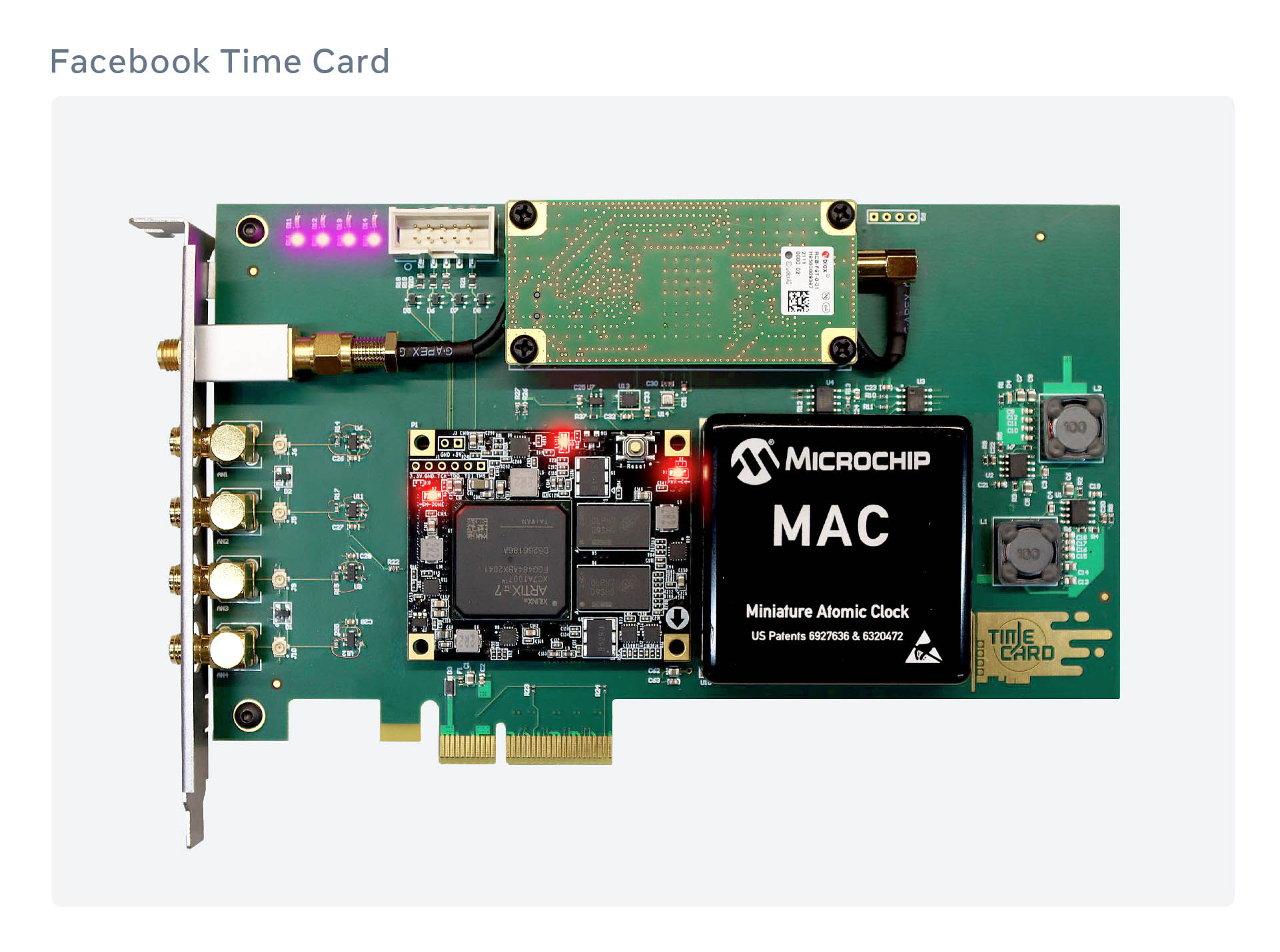
To remove these dependencies, we’ve built a new dedicated piece of hardware called Time Appliance, which consists of a GNSS receiver and a miniaturized atomic clock (MAC). Users of time appliances can keep accurate time, even in the event of GNSS connectivity loss. While building our Time Appliance, we also invented a Time Card, a PCIe card that can turn any commodity server into a time appliance.
Why do we need a new time device?
Off-the-shelf time appliances have their own benefits. They work right out of the box and because many of these devices have been on the market for decades, they are battle-tested and generally stable enough to work without supervision for a long time.
However, these solutions also come with trade-offs:
- In most cases, they are outdated and often vulnerable to software security concerns. Feature requests and security fixes may take months or even years to implement.
- These devices come with closed source software, which makes configuring and monitoring them limited and challenging. While configuration is done manually via a proprietary CLI or Web UI, monitoring often uses SNMP, a protocol that was not designed for this purpose.
- They include proprietary hardware that is not user-serviceable. When a single component breaks, there is no easy way to replace it. You have to either ship it to the vendor for repair or buy an entire new appliance.
- Since off-the-shelf devices are made in low quantities, they come with a higher markup and can become very costly to operate over time. The high cost associated with off-the-shelf devices create limitations for many in the industry. An open source version would open the door to broader applications.
Until now, companies have had to accept these trade-offs and work within the constraints described above. We decided it was time to try something different, so we took a serious look at what it would take to build our new Time Appliance — specifically, one using the x86 architecture.
Prototyping the Time Appliance
Here’s a block diagram of what we envisioned:
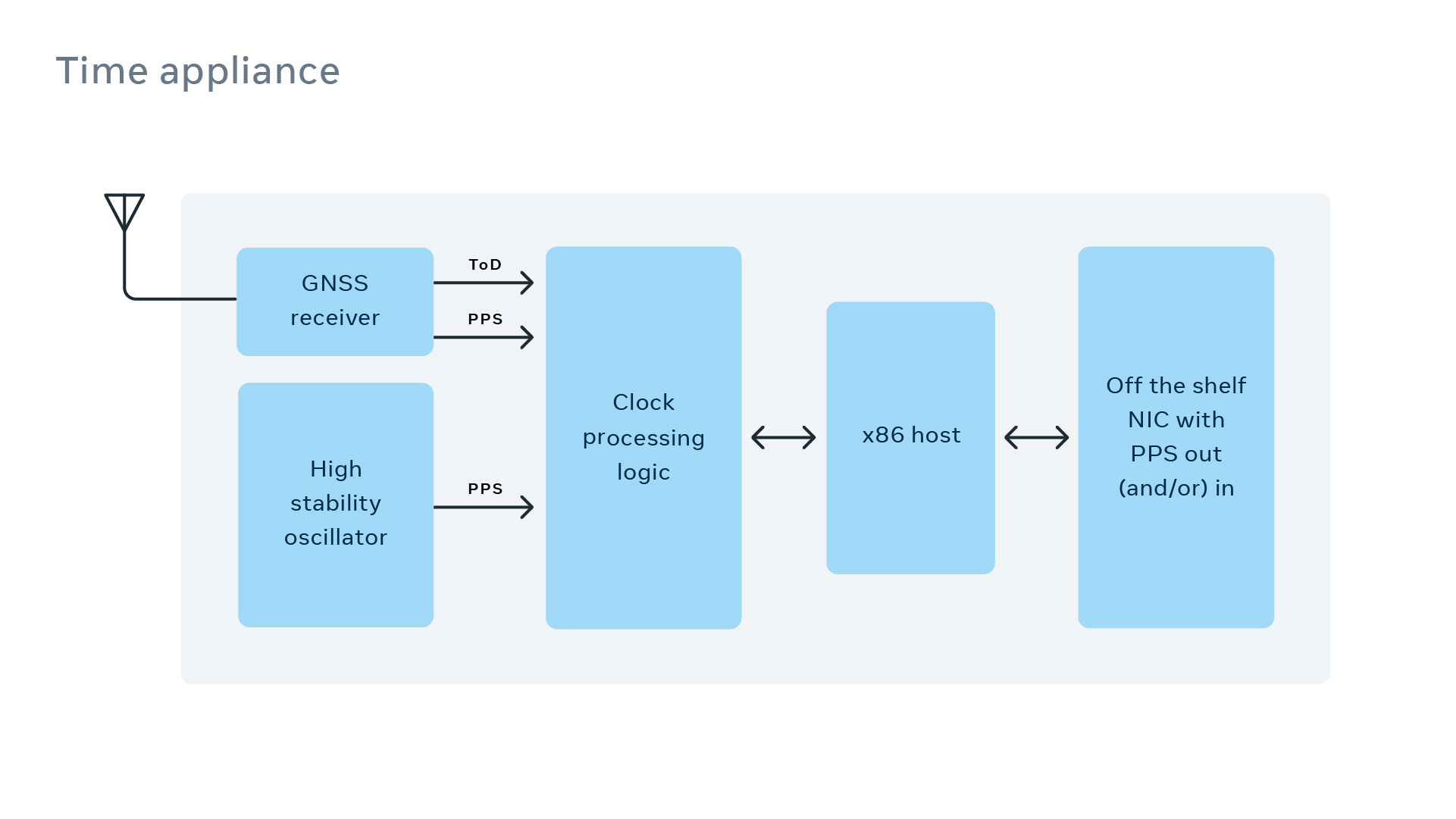
It all starts from a GNSS
receiver that provides the time of day (ToD) as well as the one pulse
per second (PPS). When the receiver is backed by a high-stability
oscillator (e.g., an atomic clock or an oven-controlled crystal
oscillator), it can provide time that is nanosecond-accurate. The time
is delivered across the network via an off-the-shelf network card which
supports PPS in/out and hardware time stamping of packets, such as the
NVIDIA Mellanox ConnectX-6 Dx used in our initial appliance.
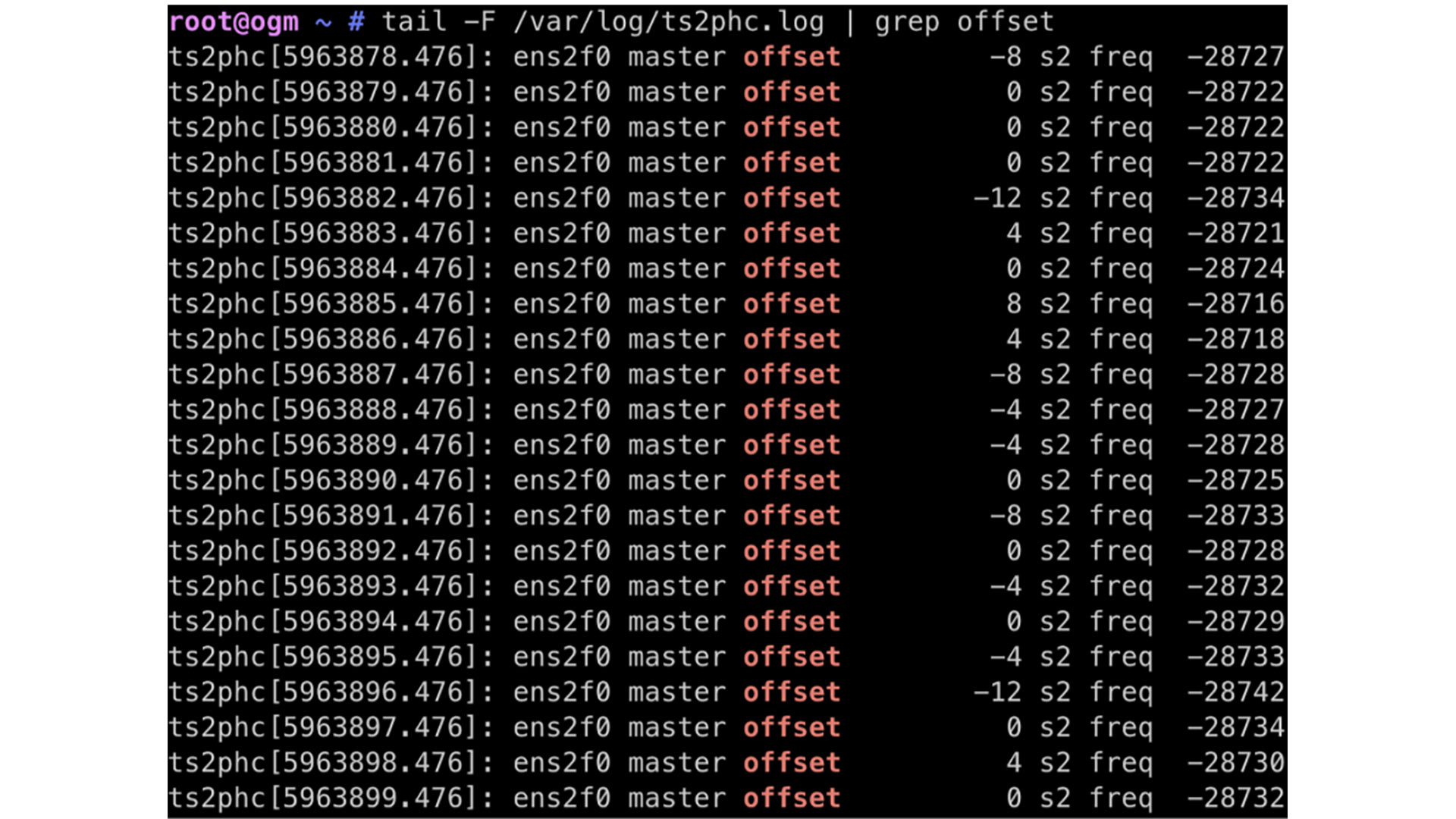
The output of the GPS disciplined oscillator (GPSDO) was fed into the EXT time-stamping of the ConnectX-6 Dx network card. In addition, the GNSS receiver provides the ToD via a serial port and a popular GPS reporting protocol called NMEA. Using ts2phc tool allowed us to synchronize the physical hardware clock of the network interface controller (NIC) down to a couple of tens of nanoseconds, as shown below:
Our prototype gave us confidence that building such an appliance was possible. However, there was a lot of room for improvement.
To increase the reliability of the system, we divided it into two major parts: payload and delivery. The payload is the precision time that is essentially an interpolation system driven by a local oscillator to create nanoseconds of time measurement between consecutive PPS signals received by the GNSS receiver. We considered putting the GNSS receiver, the high-stability local oscillator, and the necessary processing logic into a PCIe form factor, and we called it the Time Card.
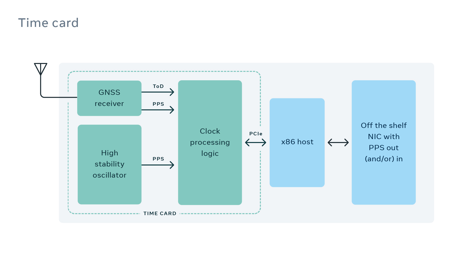
Here is the sketch of the Time Card we initially envisioned on a napkin:
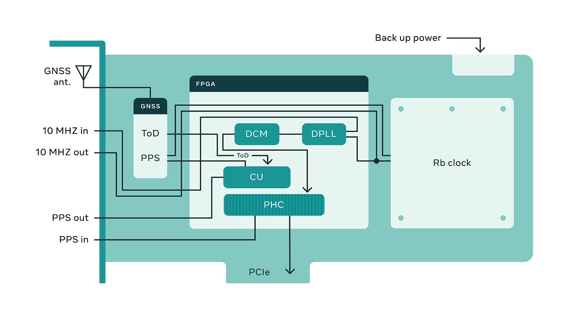
We used an onboard MAC, a multiband GNSS receiver, and a field-programmable gate array (FPGA) to implement the time engine. The time engine’s job is to interpolate in nanoseconds the granularity required between consecutive PPS signals. The GNSS receiver also provides a ToD in addition to a 1 PPS signal. In the event of the loss of GNSS reception, the time engine relies on the ongoing synchronization of the atomic clock based on an average ensemble of the consecutive PPS pulses.
The time engine consists of a set of processing blocks implemented on the FPGA of the Time Card. These processing blocks include various filtering, synchronization, error checking, time-stamping, and PCIe-related subsystems to allow the Time Card to perform as a system peripheral that provides precision time for the open time server.
It should be noted that the accuracy of a GNSS receiver is within tens of nanoseconds, while the required ongoing synchronization (calibration) of the MAC is within 10 picoseconds (1,000 times more accurate).
At first, this sounds impossible. However, the GNSS system provides timing based on continuous communication with standard time. This ability allows the GNSS onboard clock to be constantly synchronized with a source of time provided to its constellation, giving it virtually no long-term drifting error. Therefore, the MAC’s calibration is performed via a comparison of a MAC-driven counter and the GNSS-provided PPS pulse. Taking more time for the comparison allows us to achieve a higher precision of calibration for the MAC. Of course, this is with the consideration that the MAC is a linear time invariant system.
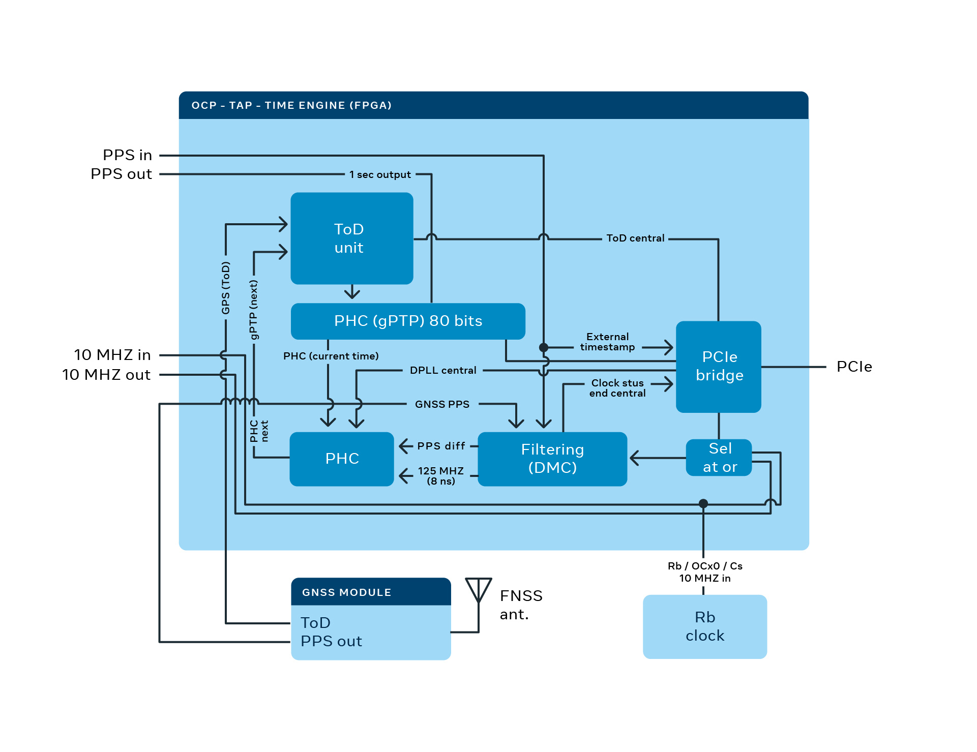
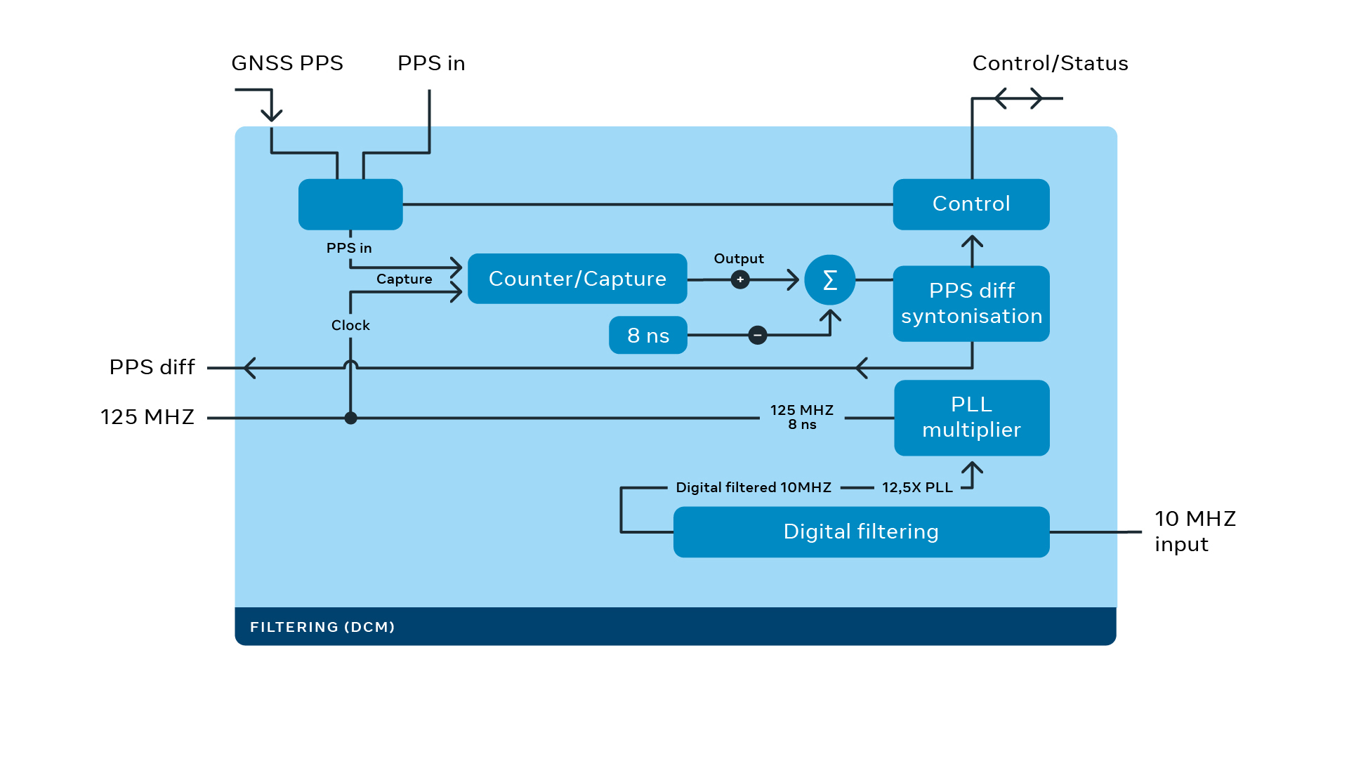
In this block diagram, you can see a 10 MHz signal from the rubidium clock entering the time engine. This clock signal can be replaced by a 10 MHz SMA input. The clock signal feeds into a digital clock module and a digital PLL (12.5x resulted from 25 up and divided by 2), resulting in a 125 MHz frequency. The 125 MHz (8-nanosecond periods) feeds into the ToD unit.
The ToD unit associates the 8-nanosecond increments in digital values of 0b000001 since the LSB (least significant bit) is associated to 250 picoseconds (driven from 32 bits of subsecond accuracy on the gPTP).
On the other hand, the PPS signal coming filtered from the GNSS is used to snapshot the result of the increments. If the 125 MHz is accurate, the accumulated increments should result in exactly 1-second intervals. However, in reality, there is always a mismatch between the accumulated value and a theoretical 1-second interval.
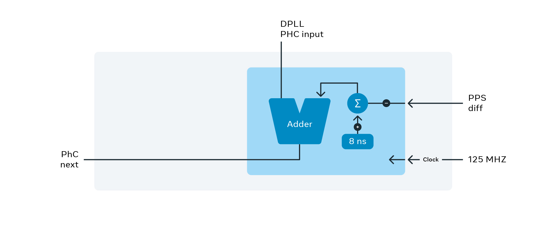
The values can be adjusted using
an internal PI (proportional and integral) control loop. The adjustment
can be done by either altering the 0b000001 value by steps of 250
picoseconds or fine-tuning the 12.5x PPL. In addition, further (more
finely tuned) adjustments can be applied by steering the rubidium
oscillator.
The longer a GNSS isn’t available, the more time accuracy is lost. The rate of the time accuracy deterioration is called holdover. Usually, holdover is described as a timeframe for accuracy and how long it takes to exceed it. For example, the holdover of a MAC is within 1 microsecond for 24 hours. This means that after 24 hours, the time accuracy is nondeterministic but accurate within 1 microsecond.
As an alternative approach, we are counting on the new generation of chip-scale and miniaturized atomic clocks with their capability to receive PPS inputs. This allows the time engine of the Time Card to hand off the ultraprecision syntonization of the high-stability oscillator to the component rather than use digital resources to reach the target.
As a general principle, the more accurate the tuning, the better the holdover performance that can be achieved. In terms of delivery, using a NIC with precision timing ensures that network packets receive very accurate time stamps, which is critical for keeping the time precise as it is shared with other servers across the network. Such a NIC can also receive a PPS signal directly from the Time Card.
After conceptualizing the idea and various implementation iterations, we were able to put together a prototype.
The Time Appliance in action
The Time Card allows any x86 machine with a NIC capable of hardware time-stamping to be turned into a time appliance. This system is agnostic to whether it runs for NTP, PTP, SyncE, or any other time synchronization protocol, since the accuracy and stability provided by the Time Card is sufficient for almost any system.
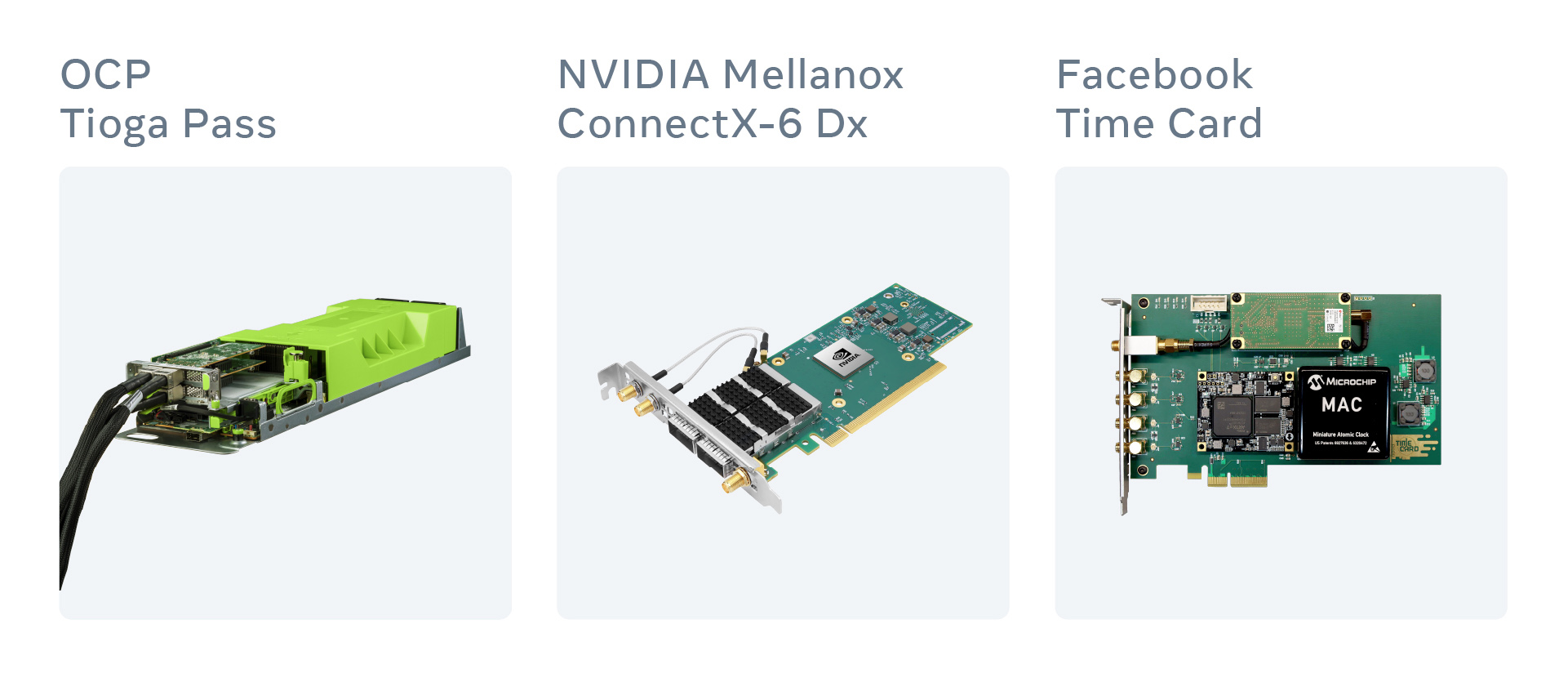
The beauty of using PCIe cards is that
the setup can be assembled even on a home PC, as long as it has enough
PCIe slots available.
The next step would be to install Linux. The Time Card driver is included in Linux kernel 5.15 or newer. Or, it can be built from the OCP GitHub repository on kernel 5.12 or newer.
The driver will expose several devices, including the PHC clock, GNSS, PPS, and atomic clock serial:
$ ls -l /sys/class/timecard/ocp0/
lrwxrwxrwx. 1 root    0 Aug  3 19:49 device -> ../../../0000:04:00.0/
-r--r--r--. 1 root 4096 Aug  3 19:49 gnss_sync
lrwxrwxrwx. 1 root    0 Aug  3 19:49 i2c -> ../../xiic-i2c.1024/i2c-2/
lrwxrwxrwx. 1 root    0 Aug  3 19:49 pps -> ../../../../../virtual/pps/pps1/
lrwxrwxrwx. 1 root    0 Aug  3 19:49 ptp -> ../../ptp/ptp2/
lrwxrwxrwx. 1 root    0 Aug  3 19:49 ttyGNSS -> ../../tty/ttyS7/
lrwxrwxrwx. 1 root    0 Aug  3 19:49 ttyMAC -> ../../tty/ttyS8/
The driver also allows us to monitor
the Time Card, the GNSS receiver, and the atomic clock status and flash a
new FPGA bitstream using the devlink cli.
The only thing left to do is to
configure the NTP and/or PTP server to use the Time Card as a reference
clock. To configure chrony, one simply needs to specify refclock attribute:
$ grep refclock /etc/chrony.conf
refclock PHC /dev/ptp2 tai poll 0 trust
And enjoy a very precise and stable NTP Stratum 1 server:
$ chronyc sources
210 Number of sources = 1
MS Name/IP address         Stratum Poll Reach LastRx Last sample
===============================================================================
#* PHC0                          0   0   377     1     +4ns[   +4ns] +/-
36ns
For the PTP server (for example, ptp4u) one will first need to synchronize Time Card PHC with the NIC PHC. This can be easily done by using the phc2sys tool which will sync the clock values with the high precision usually staying within single digits of nanoseconds:
$ phc2sys -s /dev/ptp2 -c eth0 -O 0 -mFor greater precision, it’s recommended to connect the Time Card and the NIC to the same CPU PCIe lane. For greater precision, one can connect the PPS output of the Time Card to the PPS input of the NIC.
To validate and confirm the precision, we’ve used an external validation device called Calnex Sentinel connected to the same network via several switches and an independent GNSS antenna. It can perform PPS testing as well as NTP and/or PTP protocols:
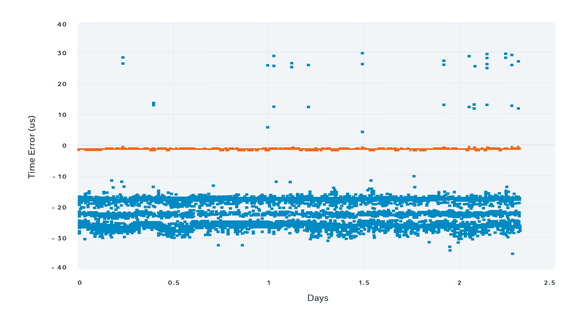
The blue line represents NTP measurement results. The precision stays within ±40 microseconds throughout the 48-hour measurement interval.
The orange line represents PTP measurement results. The offset is practically 0 ranging within nanoseconds range.
Indeed, when we compare 1 PPS between Time Card output and the internal reference of the Calnex Sentinel, we see that the combined error ranges within ±200 nanoseconds:
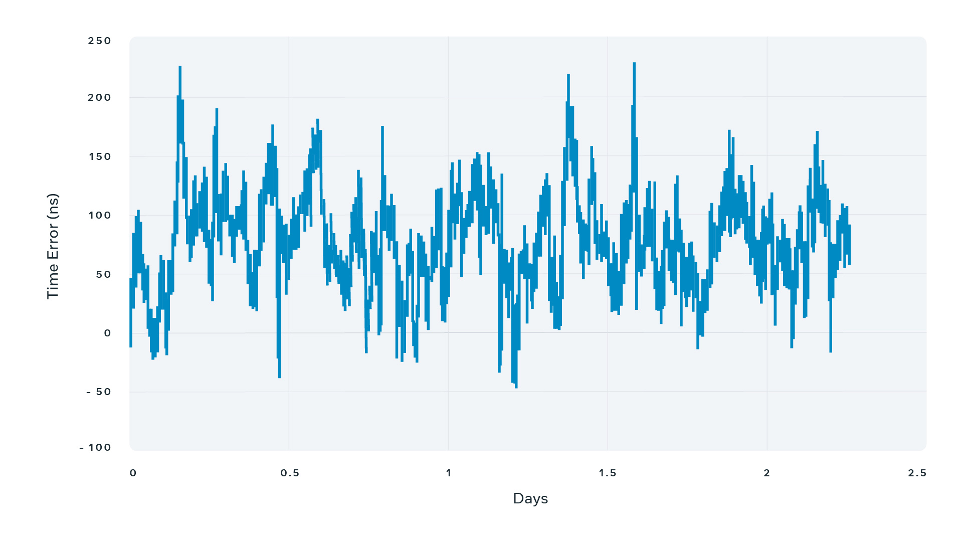
But what’s even more important is that these measurements demonstrate stability of the Time Appliance outputs.
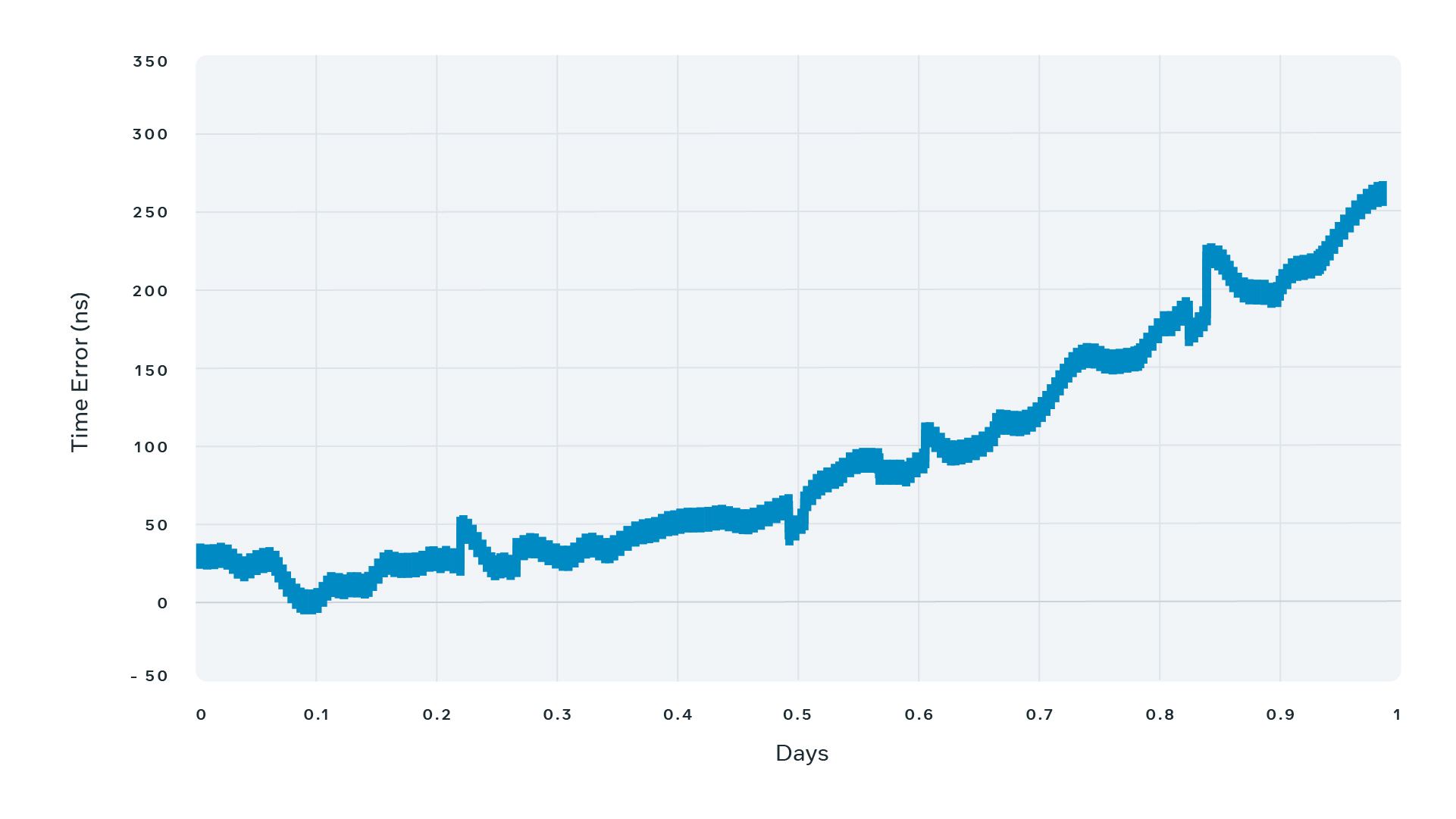
In the event of the GNSS signal loss, we need to make sure the time drift (aka holdover) of the atomic-backed Time Card stays within 1 microsecond per 24 hours. Here is a graph showing the holdover of the atomic clock (SA.53s) over a 24-hour interval. As you can see, the PPS drift stays within 300 nanoseconds, which is within the atomic clock spec.
The modular design of the Time Card allows the swap of the atomic clock with an oven-controlled crystal oscillator (OCXO) or a temperature compensated crystal oscillator (TCXO) for a budget solution with the compromise on the holdover capabilities.
Open-sourcing the design of the Time Appliance
Building a device that is very precise, inexpensive, and free from vendor lock was an achievement on its own. But we wanted to have a greater impact on the industry. We wanted to truly set it free and make it open and affordable for everyone, from a research scientist to a large cloud data center. That’s why we engaged with the Open Compute Project (OCP) to create a brand-new Time Appliance Project (TAP). Under the OCP umbrella, we open-sourced at the Time Appliance Project GitHub repository, including the specs, schematics, mechanics, BOM, and the source code. Now, as long as printing the PCB and soldering tiny components does not sound scary, anyone can build their own Time Card for a fraction of the cost of a regular time appliance. We also worked with several vendors such as Orolia who will be building and selling time cards, and NVIDIA who are selling the precision timing-capable ConnectX-6 Dx (and the precision timing-capable BlueField-2 DPU).
We published an Open Time Server spec at www.opentimeserver.com, which explains in great detail how to combine the hardware (Time Card, Network Card, and a commodity server) and the software (OS driver, NTP, and/or PTP server) to build the Time Appliance. Building an appliance based on this spec will give full control to the engineers maintaining the device, improving monitoring, configuration, management, and security.
The Time Appliance is an important step in the journey to improve the timing infrastructure for everyone, but there is more to be done. We will continue to work on other elements, including improving the precision and accuracy of the synchronization of our own servers, and we intend to continue sharing this work with the Open Compute community.
Comments
Post a Comment